This update is about some problems I encountered while building registers and an ALU for my 8-bit computer capable of running Pong. It’s part of a longer series about the build process for the whole computer.
I haven’t written a post in a long while because I’ve been absorbed in a couple of other big projects. My last update was about building three data registers and an ALU on breadboard. Since then I started testing them and discovered a variety of problems.
Firstly, there were huge drops in voltage in the breadboards that weren’t directly connected to the power supply. Some of them had ~2.5V across the power terminals, compared to 5V at the source. I had daisy-chained all the breadboards together and it was the boards furthest from the source that were showing the reduced voltage. As far as I can tell, it’s a result of the poor quality of the breadboards I was using, and the shoddy connections they have with inserted wires.
Secondly, there were problems with poor data connections. These were manifesting as quickly flickering LEDs (multiple times a second) and LEDS that would suddenly go off when you jogged the table. Given the complexity of the project, and the prototype quality of the tools I’m using, this isn’t surprising. But it is a concern. I don’t fancy debugging those kinds of problems when the clock is running at multiple kHz.
The fix
Given these problems were caused by using lower quality prototyping gear, breadboards no longer seem suitable for this project.
Instead, I decided to start implementing the project on stripboard. Breadboard is a plug-and-play tool where wires inserted into the same row are connected. Stripboard uses the same concept but has soldered connections which are more reliable but more permanent (and therefore less suitable for prototyping).
From now, I’m going to keep prototyping each component on breadboard, then implement it on stripboard when I’m sure that I won’t need to change its functionality or connections.
The build
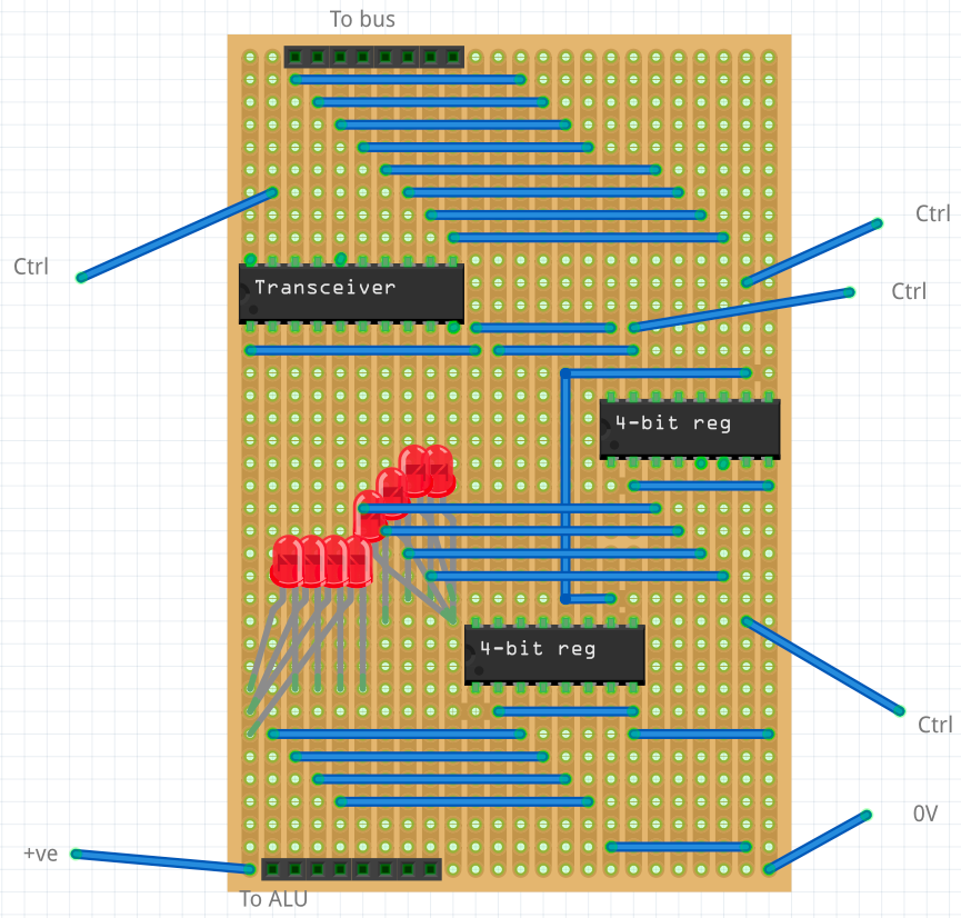
I’ve been starting with the registers. To begin with, I drew up a circuit diagram for the stripboard in an app called Fritzing. There were two big benefits compared to drawing this by hand: firstly in the ease of moving components around and trying out different configurations, and secondly in the ease of checking that all the right pins are connected to each other. When you click a pin in Fritzing, all other pins that are directly connected to it are momentarily highlighted - much easier to check your design.
Here’s the final layout I’m using, which aims to minimise crossing wires and results in a visually clear board.
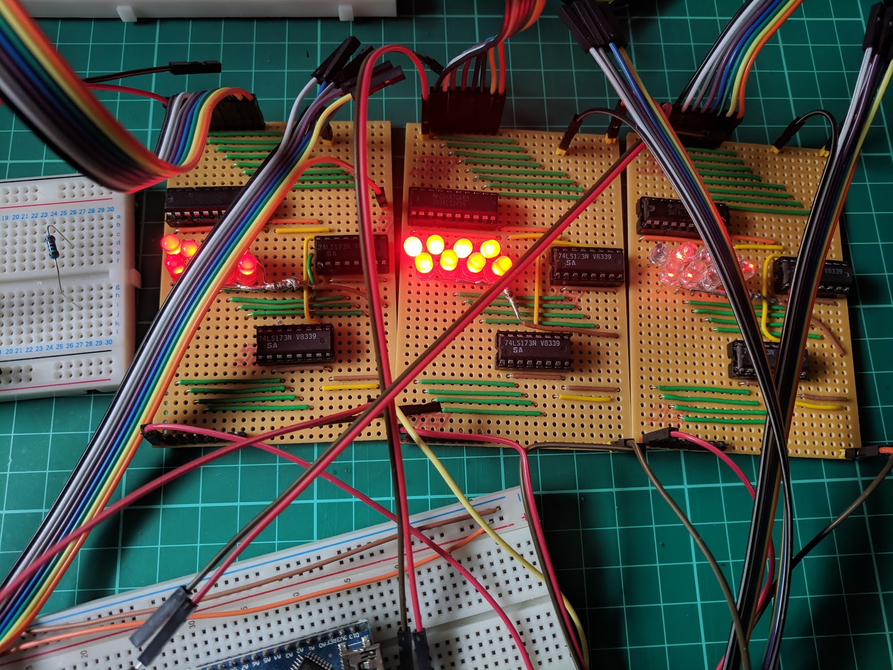
Once I was happy with the layout, I started building the registers on stripboard. It’s been fun getting back into soldering, and debugging with a multimeter!
Here’s what I have now. Two registers are fully working, and the last one needs a little more attention before it’s ready.
Next up: I’m going to be testing and fixing any problems on these. Then I’ll move onto the ALU and status register, and start building that on stripboard. I’d also like to improve the wiring between boards (it’s a mess!), so will probably use some long strips of breadboard to make a 12-channel bus (8 data channels, 5V, 0V, reset, clock).