I’m building an 8-bit computer capable of running Pong! This post is about my first steps with getting the display working.
Choosing a display, the philosophy of the project
In my last post, I settled on a display to use, but after a helpful conversation on Twitter, I realised that this probably wasn’t the right display for me. It only had a serial interface, which felt like a downside because I’d only be able to send one bit of data at a time, meaning it would take more clock cycles to write the image. But the real nail in the coffin was discovering that the computer would need to include a graphics buffer because the display didn’t have one of its own. Even for that small display, the graphics buffer would need almost all of the RAM available.
This raises a question about the philosophy of the project. Am I comfortable with buying a display unit with lots of bells and whistles, or does that defeat the point of building a computer from scratch?
After a bit of thought, I decided I was pretty comfortable buying in components that felt ancillary rather than core to the computer. Maybe by the time I finish the build, I’ll feel competent to build those kinds of things from scratch, but building all the other components of the computer feels like enough of a challenging project for now.
I’m also buying in one other component: the power supply. A power supply would be much easier to build than a display, but it just doesn’t interest me as a challenge.
The new display
Starting the search for the display again, I landed on the Adafruit 2.8” TFT LCD. It has a parallel 8-bit interface, and it also has 18-bit colour and a touchscreen which could be fun if I ever extend the project beyond Pong. It also has a “window” function to make it easy to update smaller areas of the whole display.
More importantly, it has its own graphics buffer and has good documentation. The datasheet on the controller seems clear, and Adafruit provide an Arduino library for it. Now that library can’t be integrated with my project (I’m not using a higher-level device like Arduino or Raspberry Pi), but it is a useful working example of the display in action for me to refer to.
It’s worth noting that the new display does cause some extra problems - two bytes are required per pixel, because the display supports 16-bit colour. And it’s 320 pixels wide, which is a bigger number than I can store in a single 8-bit number. I think those problems are worth taking on, to have a nice & usable display.
Oops
I had a bit of a false start the first time I soldered the mount to the display.
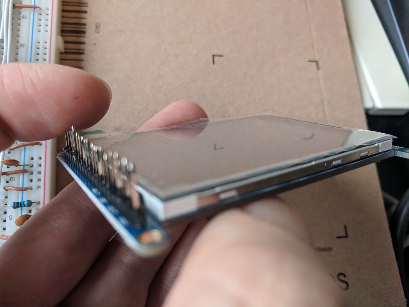
The longer side of the pin goes down into the breadboard, so if the longer side of the pin is on the same side of the board as the display, no-one is going to be able to see anything.
Facepalm.
Making sure I can control the display
I decided my first step should be to make sure that I understand the display well enough to get something showing on there, even if it’s very basic.
To start with, I read through the relevant bits of the datasheet. In summary:
- There are some pins that can just be held in a constant state
- GND low, VIN high
- IM0, 1, 2 and 3 are held low (to select the 8-bit parallel interface)
- RDX held high - if you’re reading data out of the display, you need to change it. I’m not going to be doing that.
- There’s a reset pin (RST) which is normally high, but needs to be low while the display is powered on, and then brought high afterwards.
- There’s a chip select pin (CS), held low when you want to communicate with the display.
- The command / data pin (C/D) is low when you’re inputting a command, and 1 when inputting data.
- The write pin (WRX) needs to be strobed from low to high when data is being written.
My other source is the Adafruit library for Arduino. I walked through each line of code that would run when initialising the display and drawing some pixels.
- Set CS low (to enable the chip)
- Set RST low, wait 2ms
- Set RST high (to do a hardware reset), wait 200ms
- Send command 0x01 (a software reset)
- Send command 0x28 (display off)
- Send some power / voltage control commands which I decided I could ignore
- Send some memory control commands to set the order pixels are updated, which I’m ignoring
- Send command 0x3a and data 0x55 to set the pixel format to 2 bytes / pixel instead of 3 bytes
- Send a frame control command (which I’m ignoring)
- Send an entry mode command to configure the display’s standby mode (ignored)
- Send command 0x11 to turn sleep mode off
- Send command 0x29 to turn the display on
- Send commands to set the area of screen to be updated (which I’ll need to do later but not now)
- Draw some pixels by sending command 0x2c (to write memory), then send two bytes of data for each pixel.
For my testing, I’m going to do a reduced version of this. It’s pretty laborious because I’m inputting all of these things by plugging and unplugging jumpers, then pressing a button attached to the write pin for the chip to read my data.
It’ll be faster when I can automate this with code: I’ve been playing with the resistors and capacitor of the automatic clock to make it run faster, and it’s now going at about 11kHz which should be just about enough for running Pong.
- Keep CS low, manually take RST low then high again.
- Enter command 0x01 (soft reset)
- Command 0x3a, data 0x55 (to set 2 bytes / pixel)
- Command 0x11 (sleep mode off)
- Command 0x29 (display on), which is the first time the appearance of the display changes
- Command 0x2c (start writing)
- Enter some random data, 2 bytes at a time, and see if pixels start changing colour
- Use the automatic clock instead of the manual clock to do that faster, and fill the screen.
I manually input all of those commands and data and, sure enough, it works! I took a quick video of it in action (and slowed the clock right down in the middle so you can see individual pixels changing).
Got the display working from hardware - progress! pic.twitter.com/kgCABqXZvU
— Hywel Carver (@h_carver) January 14, 2018
What’s next?
Now that I’m comfortable that I can get the display working, I’m going to put it to one side and build more of the rest of the computer. The next step will be to build the registers.